
Description
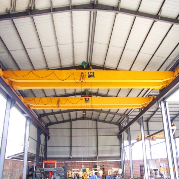
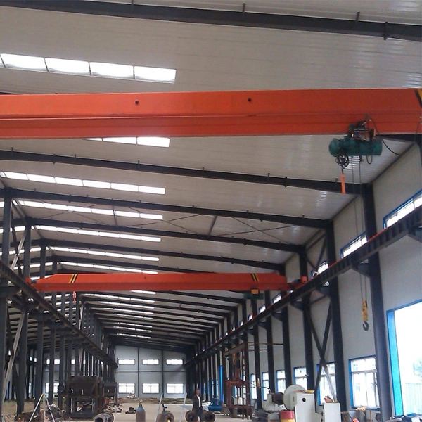
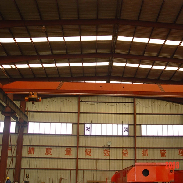
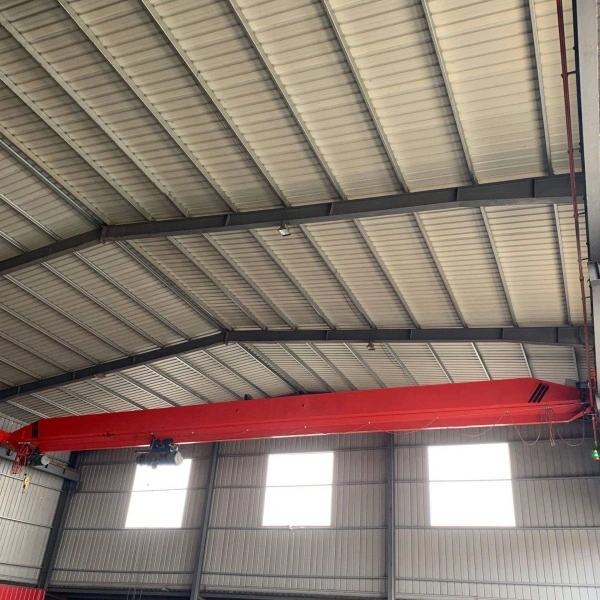
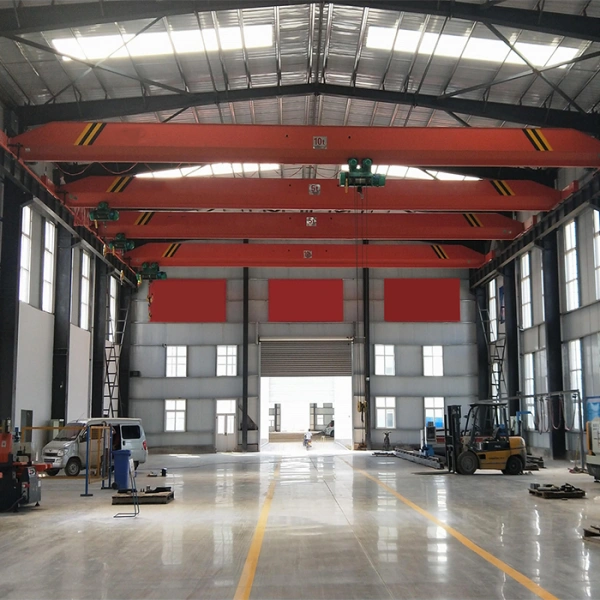
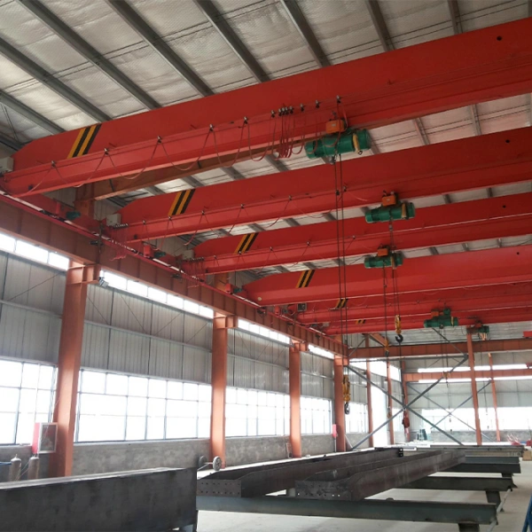
Bridge crane is a lifting equipment that is placed horizontally over workshops, warehouses and yards for lifting materials. Because its two ends are located on tall cement pillars or metal supports, it looks like a bridge. The bridge of the bridge crane runs longitudinally along the tracks laid on the elevated structures on both sides, making full use of the space under the bridge to lift materials without being hindered by ground equipment. It is the most widely used and most numerous type of lifting machinery.
Working Condition
- Metal structures and mechanical parts should have sufficient strength, stiffness and buckling resistance.
- It is required that parts and metal structures are not damaged after being loaded. For parts such as steel wire ropes with complex stress states, static strength calculations are usually carried out based on the main load and main deformation form, and a higher safety factor is used. It must also be required that the deformation of the component under the action of the load is within the allowable range, that is, There should be sufficient stiffness. Second, the whole machine must have the necessary stability against overturning.
- The prime mover has the power to meet the operating performance requirements, and the braking device should provide the necessary braking torque.
Features
FEATURE 1
Small Gantry Crane has the characteristics of being lightweight and flexible, and can be moved by its own power or trailer to meet the needs of different workplaces.
FEATURE 2
The small mobile gantry crane is equipped with operation control equipment, such as a control console or remote control, which can achieve precise lifting and handling operations.
FEATURE 3
Operators can control the lifting and lowering, forward and backward movement, and lateral expansion and contraction of the crane by controlling the equipment.
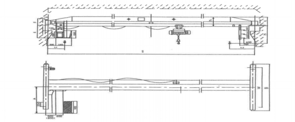
Technical Data
| (t) Lifting weight | (m) S span | G(t) total weight ground control | Rmax(KN) Max wheel load | Rmin(KN) min wheel load | H1 Wheel tread approach to top | H2 Wheel tread approach to center of hook | H3 Total height of main girder | B End carriage wheelbase | BQ Total length of end carriage | C1 Hook approach to limit position on the left | C2 Hook approach to limit position on the right |
| 5 | 7.5 | 2.20 | 28.7 | 4.6 | 580 | 1640 | 720 | 2000 | 2500 | 841.5 | 1310 |
| 8 | 2.27 | 29.0 | 4.7 | ||||||||
| 8.5 | 2.33 | 29.3 | 4.9 | ||||||||
| 9 | 2.40 | 29.7 | 5.0 | ||||||||
| 9.5 | 2.46 | 30.0 | 5.2 | ||||||||
| 10 | 2.53 | 30.2 | 5.3 | ||||||||
| 10.5 | 2.59 | 30.5 | 5.5 | ||||||||
| 11 | 2.66 | 30.8 | 5.6 | ||||||||
| 11.5 | 2.91 | 31.5 | 6.3 | 660 | 800 | ||||||
| 12 | 2.98 | 31.8 | 6.4 | ||||||||
| 12.5 | 3.05 | 32.0 | 6.6 | ||||||||
| 13 | 3.12 | 32.3 | 6.8 | ||||||||
| 13.5 | 3.20 | 32.5 | 6.9 | ||||||||
| 14 | 3.27 | 32.8 | 7.1 | ||||||||
| 14.5 | 3.52 | 33.5 | 7.7 | 785 | 1635 | 920 | 2500 | 3000 | |||
| 15 | 3.60 | 33.7 | 7.9 | ||||||||
| 15.5 | 3.68 | 33.9 | 8.1 | ||||||||
| 16 | 3.75 | 34.2 | 8.3 | ||||||||
| 16.5 | 3.83 | 34.4 | 8.5 | ||||||||
| 17 | 3.90 | 34.6 | 8.7 | ||||||||
| 17.5 | 4.41 | 35.9 | 9.9 | 880 | 1620 | 1000 | |||||
| 18 | 4.50 | 36.2 | 10.2 | ||||||||
| 18.5 | 4.59 | 36.5 | 10.4 | ||||||||
| 19 | 4.68 | 36.7 | 10.6 | ||||||||
| 19.5 | 4.76 | 37 | 10.8 | ||||||||
| 20 | 5.23 | 38.2 | 12.0 | 920 | 1700 | 1120 | 3000 | 3500 | |||
| 20.5 | 5.33 | 38.4 | 12.2 | ||||||||
| 21 | 5.42 | 38.7 | 12.4 | ||||||||
| 21.5 | 5.51 | 38.9 | 12.7 | ||||||||
| 22 | 5.60 | 39.2 | 12.9 | ||||||||
| 22.5 | 5.70 | 39.5 | 13.1 | ||||||||
| 23 | 7.08 | 42.9 | 16.6 | 960 | 1740 | 1200 | 3500 | 4000 | |||
| 23.5 | 7.20 | 43.2 | 16.9 | ||||||||
| 24 | 7.32 | 43.6 | 17.2 | ||||||||
| 24.5 | 7.43 | 43.9 | 17.4 | ||||||||
| 25 | 7.55 | 44.2 | 17.7 | ||||||||
| 25.5 | 7.67 | 44.5 | 18.0 | ||||||||
| 26 | 9.01 | 47.9 | 21.4 | 1200 | 1700 | 1400 | 3500 | 4000 | |||
| 26.5 | 9.16 | 48.3 | 21.7 | ||||||||
| 27 | 9.30 | 48.6 | 22.1 | ||||||||
| 27.5 | 9.44 | 49.0 | 22.5 | ||||||||
| 28 | 9.58 | 49.4 | 22.8 | ||||||||
| 28.5 | 9.72 | 49.7 | 23.2 |
Spare Parts
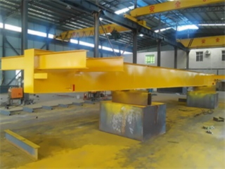
Main beam
The main beam is a box beam or H-beam structure, welded and formed from steel plates. The steel plate material is domestic steel (Q235B). The vertical winding is in accordance with Chinese national standards. All steel plates are subjected to shot blasting pre-treatment to achieve Sa2.5 level standardization. Before welding, the steel plates are carefully inspected and cleaned, usually by automatic welding machines (MIG or semi-automatic welding).
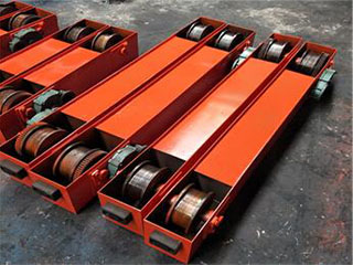
End beam
End beam is a supporting structure designed for lifting machinery, usually located at both ends of the crane, and its function is to provide stable support and balance for the crane. Cranes need to bear enormous weight and inertial forces during operation. Without the support of end beams, the crane is prone to imbalance or even overturning. Therefore, the role of the crane end beam cannot be ignored, as it is one of the key components for the safe operation of the crane.
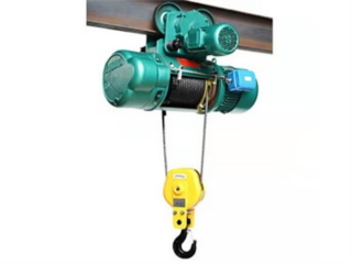
Electric hoist
The electric hoist will do dynamic and static load tests, as well as ascending and descending pressure tests. The baking paint process is used to enhance the adhesion of the paint film and improve the appearance quality. The assembly line ensures product quality.

Crane remote control
Industrial wireless remote control is a remote wireless remote control device specifically used to control construction machinery or industrial equipment.

Crane control box
The surface of the control box has undergone anti-corrosion treatment Reasonable layout for easy maintenance Protection level IP55 Environmental temperature:<45 ° C, humidity<90%.